Airsoft - Capture points (DOMINATION) - Arduino + WiFi
Airsoft is an outdoor game of radiation to extreme sports. The game is very popular, so it has also served through various styles of play, that is, game modes. Most of them are based on popular FPS titles such as Counter Strike or Call of Duty. From offensive and defensive modes to Free-for-all. One of the most popular modes is Capture Points, or DOMINATION. In this game mode, there are at least two locations that teams are fighting for.
The goal of the game is to occupy and maintain both points by one team. Points are placed in a neutral location, for example at the center of the map at the sides, or each at the headquarters of the other team. In order for the game to be fast enough, it is enough to have both points. If it is written on both points (it does not have to keep it after x seconds), the game ends and thus won. To make the game more interesting, I made these two points.
Each point contained a hardware page:


How does the system work by functionality?
One button is for Team 1 (Yellow Team) and Team 2 (Red Team) for Team One. In the event of a cast, they press their button to change the color of the point by their team. If one team has two points, the detector sounds at both points (the game ends or continues according to the organizer's rules, eg the last man for the second point for the game). The game is not time bounded by the limit.
In real time, both Arduina communicate with nRF24l01 + PA + LNA modules. The response between the two Arduins is at 1-5ms. Thanks to the nRF24l01 module, it is possible to communicate between Arduin at huge distances of hundreds of meters in an uninterrupted environment (nRF24l01 offers over 120 channels for 2.4Ghz communication.)
When using an external 5v / 3.3v source, it is possible to communicate up to 1.1 kilometers in the uninterrupted environment with the lowest transmission speed (250kbps). The program for Arduino determines the communication channel, nRF module performance, transmission rate (250kbps to 2Mbps). The higher the speed selected, the more disturbing the interference system. In the forest environment, with the lowest transmission speed and maximum transmission power, we reached 310 meters.
The principle is therefore very simple and the system can be extended by other nRF modules. One module can communicate with up to eight modules, so the system can be expanded to up to 9 points that are being fought. The highest transmission power can not be set when feeding from Arduin since the nRF subscription exceeds the controller's current characteristics. Therefore, power is used at 5-12V via the adapter into which the module is inserted and has on-board controller at 3.3V.

The module also enters the nRF24l01 module (without PA + LNA). PA + LNA is an indication for an antenna module that is 10-12 times better off than the original nRF24l01 module. The original module has a maximum range of 100 meters in an unencrypted environment with maximum power. The nRF24l01 communicates via the SPI bus and has the optional CE (Chip state) and CS (Chip select) pins. Communication is fast with low latency. These modules can only communicate with each other, they can not be used for example to connect to the Internet, These are exclusively communication modules between them at 2.4GHz. The main disadvantage of these modules is the distance of the pins from each other in both rows, which does not allow the module to be used in the breadboard. Therefore, you will not be able to develop without an adapter.
When using a buzzra, it is possible to generate the signal frequency the buzzer will output, the minimum is 31Hz and the option is to select up to 65 5XXHz. Both active and passive buzzres to Arduin are virtually the same. I would say that they are actively a little louder. From my own experience, I use 800 - 4000Hz for tone frequency, which are quite distinctive and suitable for beeping sound, not too annoying and well heard. Controlling the volume as such is not possible with such modules. When setting up a new game, both devices can be disconnected and connected to the battery / adapter, or both can be restarted by the button for removing the stored statuses of the teams to stop the detector.
Other interesting projects, including briefs about this project, can be found on my website:https://arduino.php5.sk/airsoft-wifi.php?lang=en
The solution uses the built-in SPI.h library for communication and the RF24.h library for the nRF24l01 modules. It is also possible to use the Radiohead library, which does not allow to regulate the broadcasting power and to select specific channels. pipes for the communication path, not a dialed channel number. You can try the included source codes for the functionality described above and try out this kind of game. Be careful when connecting the buttons, use the INPUT_PULLUP connection, so the button is active (pressed) at LOW - ground. This system is suitable for Airsoft, Paintball, Nerf Wars. Suitable for teams, sports grounds, etc.
Source codes are available at Github: https://github.com/martinius96/Airsoft-wifi-Arduino/tree/master
The goal of the game is to occupy and maintain both points by one team. Points are placed in a neutral location, for example at the center of the map at the sides, or each at the headquarters of the other team. In order for the game to be fast enough, it is enough to have both points. If it is written on both points (it does not have to keep it after x seconds), the game ends and thus won. To make the game more interesting, I made these two points.
Each point contained a hardware page:
- Arduino Nano/Uno
- buzzer
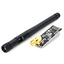
- wifi module nRF24l01 + PA + LNA
- 2 pushbuttons
- LEDs with team colors
- * Additional relay for switching stronger lights at 12V / 24V / 230V
How does the system work by functionality?
One button is for Team 1 (Yellow Team) and Team 2 (Red Team) for Team One. In the event of a cast, they press their button to change the color of the point by their team. If one team has two points, the detector sounds at both points (the game ends or continues according to the organizer's rules, eg the last man for the second point for the game). The game is not time bounded by the limit.
In real time, both Arduina communicate with nRF24l01 + PA + LNA modules. The response between the two Arduins is at 1-5ms. Thanks to the nRF24l01 module, it is possible to communicate between Arduin at huge distances of hundreds of meters in an uninterrupted environment (nRF24l01 offers over 120 channels for 2.4Ghz communication.)
When using an external 5v / 3.3v source, it is possible to communicate up to 1.1 kilometers in the uninterrupted environment with the lowest transmission speed (250kbps). The program for Arduino determines the communication channel, nRF module performance, transmission rate (250kbps to 2Mbps). The higher the speed selected, the more disturbing the interference system. In the forest environment, with the lowest transmission speed and maximum transmission power, we reached 310 meters.
The principle is therefore very simple and the system can be extended by other nRF modules. One module can communicate with up to eight modules, so the system can be expanded to up to 9 points that are being fought. The highest transmission power can not be set when feeding from Arduin since the nRF subscription exceeds the controller's current characteristics. Therefore, power is used at 5-12V via the adapter into which the module is inserted and has on-board controller at 3.3V.
The module also enters the nRF24l01 module (without PA + LNA). PA + LNA is an indication for an antenna module that is 10-12 times better off than the original nRF24l01 module. The original module has a maximum range of 100 meters in an unencrypted environment with maximum power. The nRF24l01 communicates via the SPI bus and has the optional CE (Chip state) and CS (Chip select) pins. Communication is fast with low latency. These modules can only communicate with each other, they can not be used for example to connect to the Internet, These are exclusively communication modules between them at 2.4GHz. The main disadvantage of these modules is the distance of the pins from each other in both rows, which does not allow the module to be used in the breadboard. Therefore, you will not be able to develop without an adapter.
When using a buzzra, it is possible to generate the signal frequency the buzzer will output, the minimum is 31Hz and the option is to select up to 65 5XXHz. Both active and passive buzzres to Arduin are virtually the same. I would say that they are actively a little louder. From my own experience, I use 800 - 4000Hz for tone frequency, which are quite distinctive and suitable for beeping sound, not too annoying and well heard. Controlling the volume as such is not possible with such modules. When setting up a new game, both devices can be disconnected and connected to the battery / adapter, or both can be restarted by the button for removing the stored statuses of the teams to stop the detector.
Other interesting projects, including briefs about this project, can be found on my website:https://arduino.php5.sk/airsoft-wifi.php?lang=en
The solution uses the built-in SPI.h library for communication and the RF24.h library for the nRF24l01 modules. It is also possible to use the Radiohead library, which does not allow to regulate the broadcasting power and to select specific channels. pipes for the communication path, not a dialed channel number. You can try the included source codes for the functionality described above and try out this kind of game. Be careful when connecting the buttons, use the INPUT_PULLUP connection, so the button is active (pressed) at LOW - ground. This system is suitable for Airsoft, Paintball, Nerf Wars. Suitable for teams, sports grounds, etc.
Source codes are available at Github: https://github.com/martinius96/Airsoft-wifi-Arduino/tree/master


Comments
Post a Comment