IR RPM meter with Arduino
Arduino is a platform of omnipotence. It allows to create simple flashers, but also complex systems for more advanced automation. Thanks to the different buses, the Arduino can be expanded to include different peripherals. Today we will take a closer look at the obstacle infrared sensor and its use for the tachometer. The sensor principle is very simple. It contains 2 diodes, emitting and receiving diode.
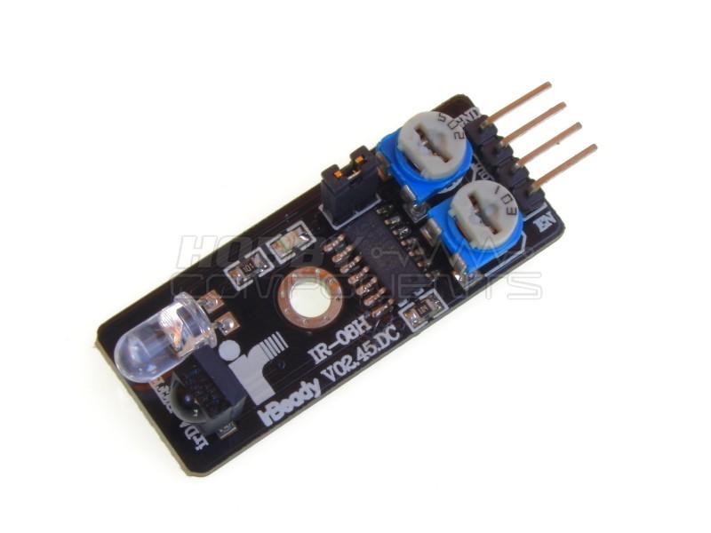
The receiving IR diode is connected directly to the 5V digital output, and a potentiometer can be used to control the sensitivity (distance of the object) to which the receiving diode will react. The module is powered by Arduino 5V, it is also used to supply a transmitting IR diode that emits light permanently at 38kHz at a wavelength of 950nm / 940nm (depending on the diode used). The module can be found at retailers (Aliexpress and others) under the name KY-032, respectively Obstacle Sensor. There are several versions, I used the first version, which is constructed very simply.

There are also more perfect versions that have multiple potentiometers, gain control, better construction, EN signal and so on. (KY-032 ver. 2)
The sensor reacts to an obstacle at a certain distance (set by a potentiometer) 2-40 cm. When an obstacle is detected, a 5V signal is applied to the output terminal of the module that processes the Arduino. One of the (in) advantages of IR diodes is that light can reflect off shiny surfaces. That is, it will detect the shiny surface at a smaller distance than the matte surface. This made me think of using this sensor differently as a tachometer. On the matt surface - the pulley of the crankshaft I glued a strip of tape about 1cm wide, or it is good to use aluminum foil, it has better reflective properties of light. I set the gain intensity so that at a constant distance from the pulley, the module only responds to the tape as it passes through the module each time the crankshaft turns, not to the pulley itself.
Arduino interrupts the signal from the module and adds a variable that is evaluated once a second by a formula that converts the read signals into the number of signals per minute. This makes it possible to determine the number of revolutions of the crankshaft (engine) per minute. Refresh the display is every second. The speed is later shown on the 20x4 character LCD display with I2C converter. Thanks to converters it is enough to connect 4 wires to the display. Power supply (5V), ground (GND), clock signal (SCL), data (SDA). The tachometer can be used for various machines, speed monitoring of pulleys of tractors, harvesters, but also in industry for monitoring of processes, operation and activity of machines.
Connection diagram for tachometer with display and infrared module KY-032:

The resulting representation might look like this:

More about the project can be found at: https://arduino.php5.sk/otackomer.php?lang=en
Program for Arduino (Uno):
#include <LiquidCrystal_I2C.h>
LiquidCrystal_I2C lcd(0x3F, 20, 4); //alebo 0x27 --> I2C adresy sa mozu roznit
float value = 0;
float rev = 0;
int rpm;
int oldtime = 0;
int time;
void isr() {
rev++;
}
void setup() {
lcd.begin();
lcd.backlight();
lcd.setCursor(0, 0);
lcd.print("-----ZETOR 4011-----");
attachInterrupt(digitalPinToInterrupt (2), isr, RISING); //interrupt pin
}
void loop() {
delay(1000);
detachInterrupt(digitalPinToInterrupt(2));
time = millis() - oldtime; //rozdiel casov
rpm = (rev / time) * 60000; //vyrataj otacky/min
oldtime = millis(); //uloz aktualny cas
rev = 0;
lcd.setCursor(0, 1);
lcd.print(rpm);
lcd.print(" ot/min");
attachInterrupt(digitalPinToInterrupt (2), isr, RISING);
}
The receiving IR diode is connected directly to the 5V digital output, and a potentiometer can be used to control the sensitivity (distance of the object) to which the receiving diode will react. The module is powered by Arduino 5V, it is also used to supply a transmitting IR diode that emits light permanently at 38kHz at a wavelength of 950nm / 940nm (depending on the diode used). The module can be found at retailers (Aliexpress and others) under the name KY-032, respectively Obstacle Sensor. There are several versions, I used the first version, which is constructed very simply.
There are also more perfect versions that have multiple potentiometers, gain control, better construction, EN signal and so on. (KY-032 ver. 2)
The sensor reacts to an obstacle at a certain distance (set by a potentiometer) 2-40 cm. When an obstacle is detected, a 5V signal is applied to the output terminal of the module that processes the Arduino. One of the (in) advantages of IR diodes is that light can reflect off shiny surfaces. That is, it will detect the shiny surface at a smaller distance than the matte surface. This made me think of using this sensor differently as a tachometer. On the matt surface - the pulley of the crankshaft I glued a strip of tape about 1cm wide, or it is good to use aluminum foil, it has better reflective properties of light. I set the gain intensity so that at a constant distance from the pulley, the module only responds to the tape as it passes through the module each time the crankshaft turns, not to the pulley itself.
Arduino interrupts the signal from the module and adds a variable that is evaluated once a second by a formula that converts the read signals into the number of signals per minute. This makes it possible to determine the number of revolutions of the crankshaft (engine) per minute. Refresh the display is every second. The speed is later shown on the 20x4 character LCD display with I2C converter. Thanks to converters it is enough to connect 4 wires to the display. Power supply (5V), ground (GND), clock signal (SCL), data (SDA). The tachometer can be used for various machines, speed monitoring of pulleys of tractors, harvesters, but also in industry for monitoring of processes, operation and activity of machines.
Connection diagram for tachometer with display and infrared module KY-032:
The resulting representation might look like this:
More about the project can be found at: https://arduino.php5.sk/otackomer.php?lang=en
Program for Arduino (Uno):
#include <LiquidCrystal_I2C.h>
LiquidCrystal_I2C lcd(0x3F, 20, 4); //alebo 0x27 --> I2C adresy sa mozu roznit
float value = 0;
float rev = 0;
int rpm;
int oldtime = 0;
int time;
void isr() {
rev++;
}
void setup() {
lcd.begin();
lcd.backlight();
lcd.setCursor(0, 0);
lcd.print("-----ZETOR 4011-----");
attachInterrupt(digitalPinToInterrupt (2), isr, RISING); //interrupt pin
}
void loop() {
delay(1000);
detachInterrupt(digitalPinToInterrupt(2));
time = millis() - oldtime; //rozdiel casov
rpm = (rev / time) * 60000; //vyrataj otacky/min
oldtime = millis(); //uloz aktualny cas
rev = 0;
lcd.setCursor(0, 1);
lcd.print(rpm);
lcd.print(" ot/min");
attachInterrupt(digitalPinToInterrupt (2), isr, RISING);
}


Comments
Post a Comment